
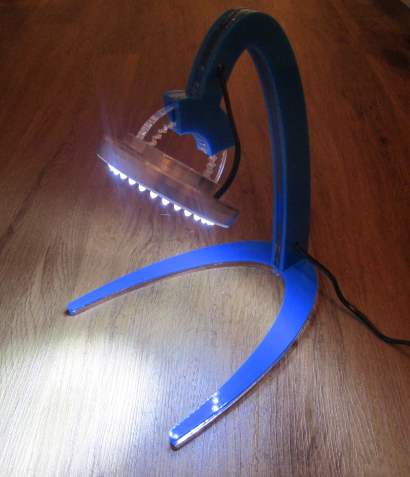
 Having grown tired of trying to solder in the gloom of the my dining room, I decided to make a table-top lamp in the hope that the quality of my soldering might improve if I could see what I was doing.
The aim was to make it as quickly and easily as possible, and to keep costs to an absolute minimum by re-purposing and recycling as many materials as I could.
The finished article ultimately cost just less than £10, and if I’d known what I was doing from the outset, it would have taken me about 4 hours to make. In reality, it took me considerably longer, but, hey, I learnt a lot along the way….
Materials and resources
- 1 x ring-shaped aluminum casing
- 30 x bright white LEDs
- 10 x 150R resistors
- 2 x A4 sheets of 7.5mm thick clear acrylic
- 1 x A4 sheet of 5mm blue acrylic
- 1 x A4 sheet of 3mm blue acrylic
- 1 x scrap piece of grey acrylic
- 1 x 2 metre length of two wire flex
- 1 x 12v DC power adapter
- a liberal amount of insulating tape
- various adhesives (incl. one small packet of Sugru)
The acrylic parts of the lamp were designed in 2D with OpenSCAD software, and cut with the laser engraver at rLab. I have since modelled them in 3D with Blender to create the renders used to illustrate the design below – if I was to start afresh I would do this step before cutting, so I could assess and tweak the design before committing to the cut. Piecing the design together in 3D gives a real insight into the look and feel of the finished item and I probably would have made a few changes to make the stand more flowing and less angular.
The LED circuit was designed using the ‘guru’ tool at LEDCalc.com.
For completeness, other tools used: soldering iron, digital calipers, drill with 5mm bit, a Dremel and some soft-grip clamps.
The basic design
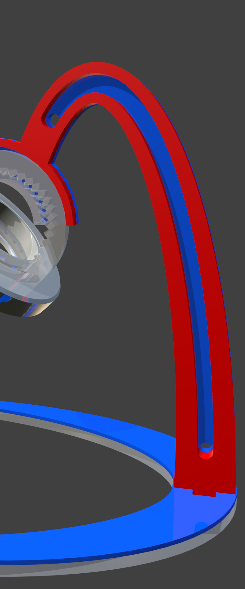 The upright part of the lamp stand is constructed from three pieces of acrylic sandwiched together – two 5mm blue, one 7.5mm clear. An advantage of sandwiching the clear acrylic between two opaque acrylic pieces is that it hides the mess that you make if you’re not used to working with the adhesives!
The clear acrylic (shown in red in the cutaway picture to the left) has a channel running through the middle for the flex to run through, so that it is safely held within the upright part of the stand to reduce the risk of me accidentally pulling the lamp over.
The foot of the stand is made from two pieces of acrylic – one 3mm blue, one 7.5mm clear.
 The head of the lamp is designed around a ring-shaped aluminium casing that I rescued from the scrap aluminium bucket at rLab. I removed the thread from the inside edge of the casing with the Dremel, so that the grey acrylic ring that holds the 30 LEDs fits snugly inside. The circuitry for the LEDs is protected with a spacer ring cut from 7.5mm acrylic.These three parts are held together with Sugru – so that I can separate them later if I need to get at the LED circuitry.
 The head is attached to the stand with two further pieces cut from 7.5mm acrylic – one a ring that fixes to the outside of the aluminium casing, the other a semi-circular piece set perpendicularly in the first, with cog teeth on the inside. This is supported by a piece of acrylic with matching set of teeth set between the two outer pieces of the lamp stand upright. There is a channel that is just big enough to allow me to reposition the head through 90 degrees.
The LED circuitry
The 30 LEDs are wired together as 10 parallel series of 3 LEDs, each with a 150R current limiting resistor. The circuit was designed using the ‘guru’ tool at LEDCalc.com. Being a novice at electronics there is no way that I would have struck upon the idea of wiring them up this way myself. The tool allows you to feed in the supply voltage, voltage drop for the LEDs, desired current and number of LEDs, and it will then generate a circuit design for you. I played with a few different input values and got a range of results, but on the basis that I had measured the output of the power supply at 12.1V, and the voltage drop of the LEDs are given as 3.2-3.5V, I figured that 150R resistors were a conservative bet. 
 Sadly I didn’t take a picture of the way that I wired up the LEDs before I smothered the circuit in insulating tape, but in essence there are two rings.
The inner ring is made from the cathodes of the final LEDs in each series of three. By good fortune, the cathodes were exactly the right length when bent over to reach to the cathode of the final LED in the next series. It was therefore a simple job of bending them over and soldering them together.
The anodes of the first LED in each series is soldered to the 150R current limiting resistor, which in turn is soldered to the outer ring which is formed of a piece of stripped hook-up wire. The insulating tape – in theory – keeps the separate parts of the circuit apart and prevents any shorts. In practice, when I first assembled the lamp, a sharp end punctured through the tape, shorting the current limiting resistor out of one of the series, burning out three of the LEDs. There’s probably a better solution.
The power is carried to the rings with a nice, long 2m flex, which I re-purposed from an old lamp. I hacked apart the 12V adapter to replace the existing cable with the flex, re-sealing the hole where the flex enters the adapter with liberal amounts of Sugru.
Creating curves in OpenSCAD
The curved feet and upright of the stand were designed in OpenSCAD by using FOR loops to create unions of hundreds of overlapping circles of gradually varying size arranged in elliptical patterns.
The first approach, which I used for the upright, involved simply unioning a sequence of circles together. Although this appeared to be OK on the screen in OpenSCAD, when it came to cutting the pieces, it resulted in (a) the laser engraver struggling to cope with the finely defined shapes, and (b) a very fine ribbing effect along the edges of the pieces. As it happens, if you look closely the ribbing can be seen in a render that I subsequently produced in Blender.

For the feet pieces I hulled together pairs of consecutive circles within the FOR loop to create a much smoother finish.
Adhesives
Finally, a word about adhesives.
By far the hardest part of the build was sticking the pieces of acrylic together, and the one piece of advice I would offer to anyone taking on a similar project would be to spend plenty fo time practising on off-cuts.
For the upright I used water-thin acrylic solvent cement. I clamped the pieces together and used a small syringe to squirt the cement into the tiny gap between the pieces. You can get a great finish with it, but be warned – this stuff is very, very runny, and you really need to concentrate on what you are doing if you are not going to end up with it smeared all over your otherwise shiny acrylic.
To fix the base, I didn’t have the acrylic cement to hand and made an adhesive paste in a jar from acrylic and dichloromethane instead (nb. well ventilated area required!). Less runny, and easier to apply, but very stringy instead.
Whichever you use, you’ll want to have a pack of wipes to hand.
